|
Introduction
I want to describe my current preamp (called L-10) and the way of its realisation.
When I start this project, a basic requirement was to build a full remote controlled preamp.
There are many way to realise a full remote controlled preamp.
I decided to build a CS3310 based preamp at first. Maybe an Aleph clone follows.
An other basic requirement was to have a open design. So the building of a
further preamp will be a less complex work, because a lot of work is already done. For example the controller: only the two software functions must be changed: select inputs, select volume, the rest need not be changed.
The
open design requires an exact description of the interaction between the controller - PSU - analogue (audio) circuit. Please see the prebus documentation as follows.
Here are the specifications for this project before it starts:
General system specification
- different housings concepts must be possible:
1. all in one
2. first housing: controller and power supply
second housing: analogue system, both channels
3. first housing: controller and power supply
second housing: right channel analogue system
third housing: left channel analogue system
- line filter
Analogue part specification
- symmetric in- and outputs, if possible
- at least 4 inputs
- record-out not needed
- full digital controlled by µC, optocouplers for isolation
Digital control specification
- full remote controlled, using Philips RC5 code, link1, link2, link3, link4, link5
- switched 12V signal to drive relays, turn on power amps etc.
- 2x16 LCD module
- 8051 based µC (Atmel AT89S8252 used)
- all of the following preamps should be possible to control:
1. L-10 project: Volume: CS3310 or PGA2310, switches SSM2404
2. Thel preamp, based on VX-pro or music-amp
3. Aleph preamp Version Aleph P1.7
The prebus
When the preamp is split over different housings, there must be a cable with connectors between all the housings. The following
signals/supply voltages must be connected:
1. power supply for analogue circuit, separated for each channel
2. power supply for digital (µC) circuit
3. Control signals between controller and PS-unit
4. Control signals between controller and analogue circuit(s)
I choose one 50 pin Centronics 1:1 connection for all voltages and signals: the Prebus V1.2.
Every housing has only one connector and there is only one cable between all housings, like SCSI.
The realisation of the L-10 project
First some pictures of the finished preamp
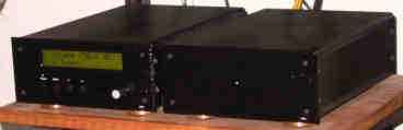
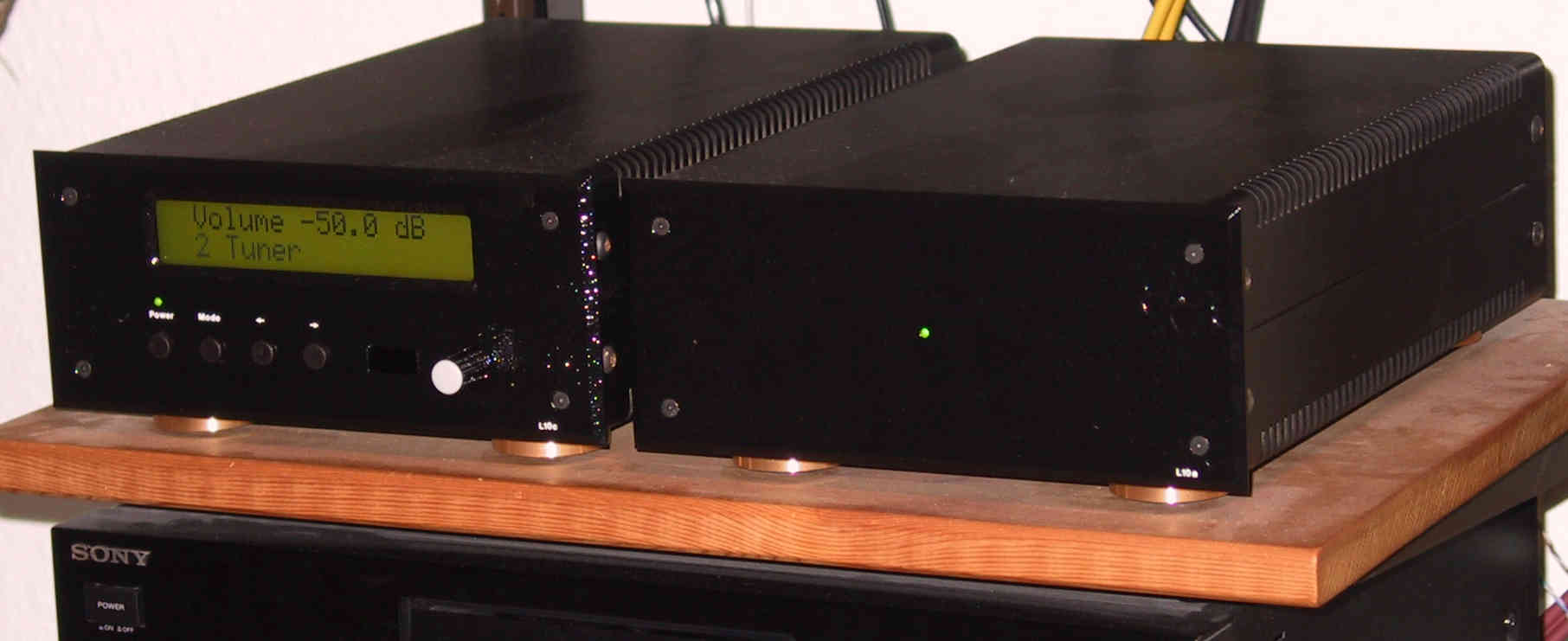
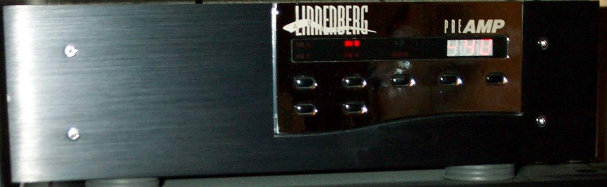
This is the finished preamp L-10.
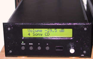
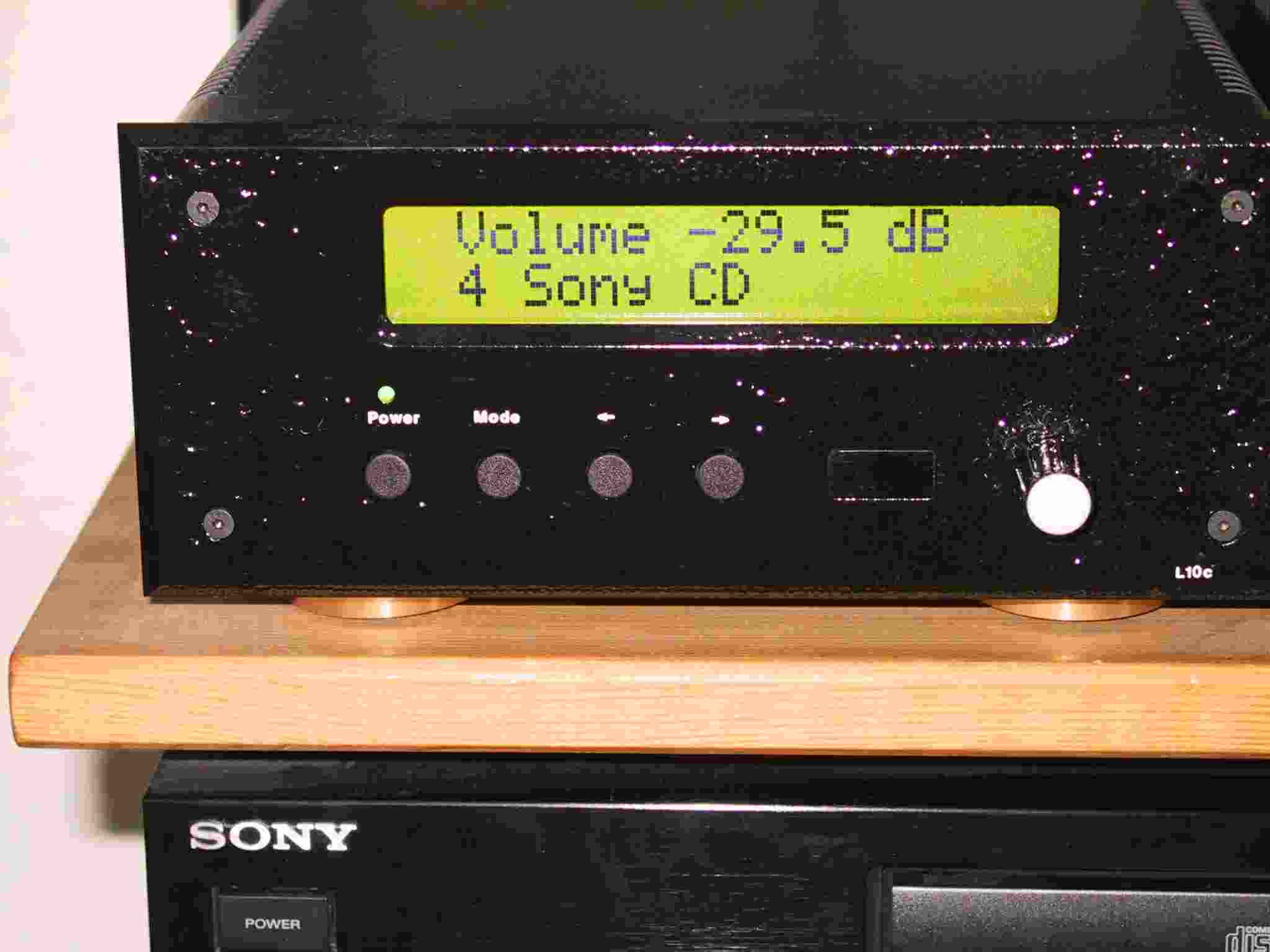
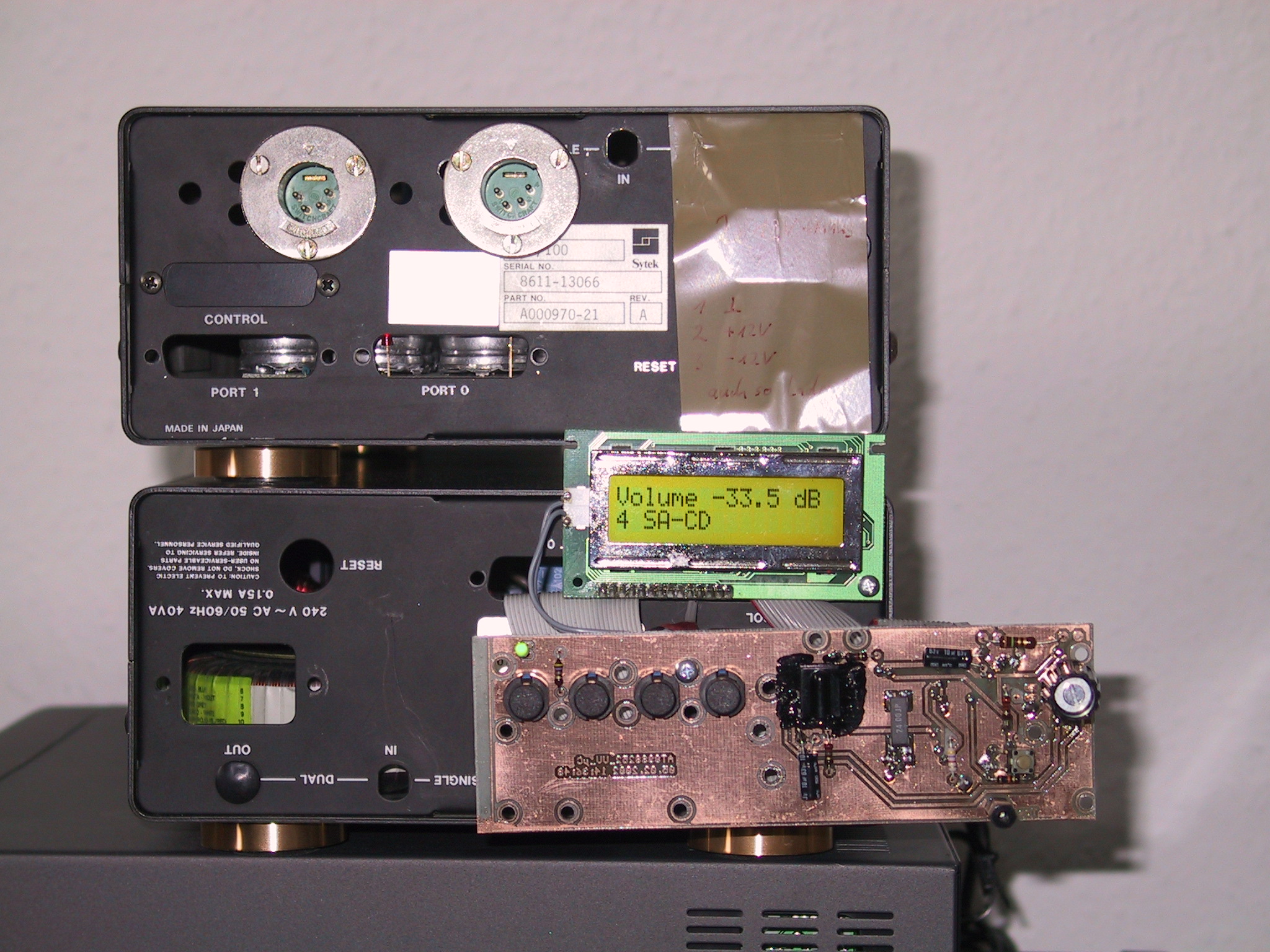
The controller with LCD.
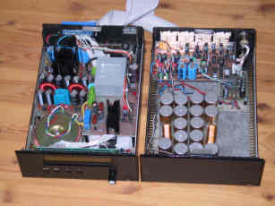
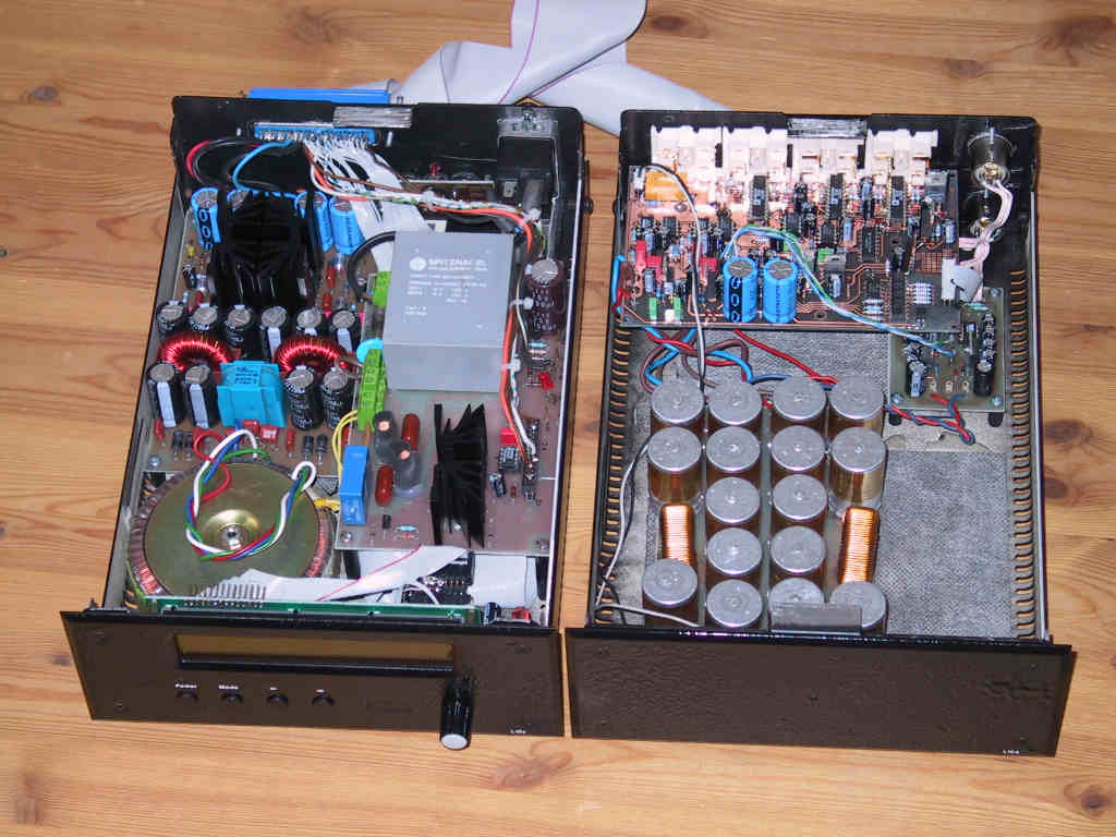
The opened housings.
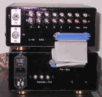
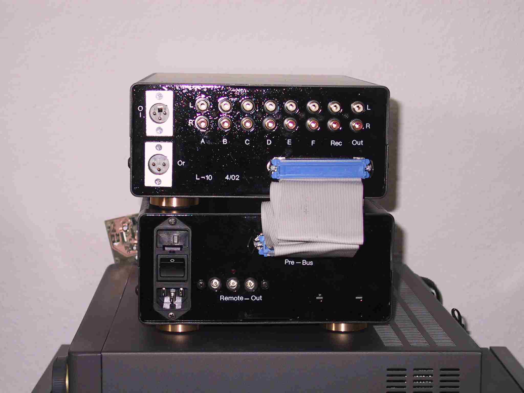
From the back
There is
a Linnenberg preamp which is nearly the same as I want to build. Dieter Achenbach has taken these pictures (picture1, picture2) of this preamp.
As you see the L-10 is split into two housings:
- the first: only analogue (audio) circuits, additional capacitors
- the second: the rest (PS, µC, keys, LCD and peripheries...)
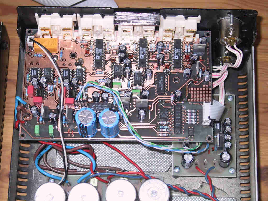
The audio circuit
audio board L10b schematics as PDF
audio board L10b picture
This circuit works as follows:
The inputs are switched, using analogue switches (SSM2404), via a 10k resistor to the inverted input of an OPA. So the switches are used in the Virtual Ground Switching mode as shown in the AD datasheet. The OPA drives a crystal volume controller CS3310. There are two outputs possible:
- symmetric (XLR) and
- asymmetric (Cynch).
The asymmetric output stage is realised on the PCB using a BUF634.
The symmetric output stage is realised on an additional PCB using TI (BB) DRV134PA or the AD SSM2142
The PCB needs only one PS (+-18,5Vdc). All used voltages are stabilised by LM317/337. There are 100nF decupling SMD capacitors at all power supply pin at all ICs.
The circuit is realised on a home made double sided 160 mm x 100 mm PCB.
The interface to the prebus-µC-signals uses optocouplers to isolate the analog from digital circuit.
The input switches SSM2404 are set by a 74HC595. This IC transform the serial prebus signals (SPI-like) to parallel signals. If you need more signals on the audio board you only have to add more 74HC595, maybe I need more for other preamps.
The power supply
There are two power supplies necessary:
1. The power supply for the analog circuit
I use here a combination of: a 300VA torodal transformer, fast diodes, pi-filter, LM317/337 as pre-regulator to +-18,5Vdc.
2. The power supply for the digital circuit
On the digital PS PCB the following functions are realised:
- +5V for the µC circuit
- about +8V for the LCD backlight
- digital power supply power fail detection
- +12V output driver, to turn external devices on and off
- relay to turn analog power supply on and off
The Controller circuit
Controller V02b Schematic.PDF
Controller_V02.jpg
The controller has to do a lot of work:
- analyse key on the front panel
- analyse encoder Bourns 3315Y on the front panel
- receive IR-remote control signals (Philips RC5 code), using SFH506-36
- display data on the LCD module
- control the audio board
The used µC is an Atmel AT89S8252-24JI (PLCC44). This µC can be programmed in circuit by the free program PonyProg. The µC software is complete written in Keil C.
Handling and the menu system
When the preamp is turned on the LCD shows:

You see the selected input: No. 4, named Sony CD
The (volume) attenuation is -29.5 dB.
You can switch to the menu mode. Then you see
the 1. menu Balance:
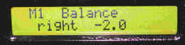
Here you can attenuate one channel in 0.5 dB steps.
The 2. menu, Backlight:

Here you can adjust the backlight intensity of the LCD backlight.
The 3. menu, Keydef:

Each input has the following attributes:
- input number: 4 -> number 1...6
- input name: Sony CD -> there are a lot of names available.
The names can be changed by using the EEPROM monitor.
- input port: F -> each input connector on the backplane has a description/name, A...F.
- attenuation, related to the selected input: --7,0 dB -> 0...-20 dB.
So every input can be attenuated in the way that all inputs have the same level.
So you can configure the preamp in the way you want. The L-10 has only Cynch input connectors but
maybe I will build a preamp with XLR and Cynch inputs. Then the function input port is useful.
For example the next preamp has 2 XLR and 4 Cynch input-connectors and I want to have:
1: CD, XLR
2. Tuner Cynch
3. DAT, XLR
4. Tape, Cynch
5. DVD, Cynch
6. Aux, Cynch
The 4. menu, Turn_ON_value:

At this menu you can change between:
- self defined: at every start the preamp starts with the same configuration. This configuration can be stored by the user.
- last turn OFF: the preamp stores the configuration at every shut down and start with this configuration.
The 5. menu, EEPROM monitor:

The data of the EEPROM can be changed here. E.g. the names and the RC5 codes.
The 6. menu, RC5 monitor:

The -> pushbutton has to be pressed to start the RC5 monitor.
Then the preamp stop its function and shows the last received RC5 address and RC5 command on the LCD.
In the RC5 code each key is defined by one command byte and one address-byte. The L-10 use
command-byte 0 (=television). So every pre-programmed remote control can be used to control the L-10. The RC5 address and commands are stored in the EEPROM and can be changed.
Project files:
The schematic and boards were made by using the CAD program eagle 3.55.
The µC program was compiled by the Keil 8051 C-compiler.
If you are interested in these files please send a mail
Please mail:
I am very interested in improving this project and this site. So if you have any ideas, please mail.
What to do:
- testing TI / Burr Brown PGA2310
- better pictures of the Controller
- realise a Aleph preamp based on Aleph P1.7
Links:
other IC: WM8816
other IC: MAS MAS9116
Jeff Rowland Design Group comments to CS3310
other preamp concept by Dave Paton
other preamp concept by Mark Hennessy and testing different ICs
|